TIPOMEGA®
premium class balcony connectors
TIPOMEGA®
premium class balcony connectors
UNUSUAL PROJECTS
In the slab above the seventh and eighth floors, the architect designed balcony slabs and canopies rigidly connected to the walls located between them. The entire structure formed a unique spatial system that required connection to the building along all contact edges using thermal insulation connectors.
The movement of the elements resulted in the simultaneous occurrence of positive and negative vertical shear forces as well as bending moments. In addition, horizontal shear forces acting parallel to the joint in both directions, as well as torsional moments, were continuously present during the works. The unique design of the TIPOMEGA connectors made it possible to transfer all these forces in an integrated manner.
UNUSUAL PROJECTS
Katowice
In the slab above the seventh and eighth floors, the architect designed balcony slabs and canopies rigidly connected to the walls located between them. The entire structure formed a unique spatial system that required connection to the building along all contact edges using thermal insulation connectors.
Stalowa Wola
The movement of the elements resulted in the simultaneous occurrence of positive and negative vertical shear forces as well as bending moments. In addition, horizontal shear forces acting parallel to the joint in both directions, as well as torsional moments, were continuously present during the works. The unique design of the TIPOMEGA connectors made it possible to transfer all these forces in an integrated manner.
Thermal bridges
Structural elements protruding from the thermal envelope of an insulated building, such as balconies, cornices, canopies, parapets, attics, etc., act as thermal bridges.
The phenomenon of vapor condensation on the inner surface of an external wall results from the fundamental principle of heat flow continuity: the rate of heat transfer increases as the cross-sectional area decreases and decreases as the cross-sectional area increases.
About
Many architects and investors have attempted to address this issue by insulating balconies with a relatively thin layer of thermal insulation, often applied only to their underside.


Unfortunately, these design solutions did not eliminate thermal bridges.
The only benefit they provided was the potential replacement of a linear thermal bridge with a point thermal bridge.

A significant drawback of using reinforced concrete beams in balcony slabs was their failure to meet fire resistance regulations for the inter-storey belt, including the connection to the ceiling.


Therefore, for over forty years, load-bearing thermal insulation connectors have been used in residential construction at the junction between balconies and buildings.

Selected legislation
Article 5 of the Building Law dictates that the building must be designed and constructed in such a way as to ensure that the requirements of the Regulation of the European Parliament and the Council of the European Union concerning energy saving and thermal insulation are met.
About
The Regulation of the Minister of Infrastructure of 12 April 2002 on the technical conditions to be met by buildings and their location imposes limits on the degree of impact.

The Technical Conditions use the dimensionless temperature coefficient fRsi.
This gives an advantage of a parametric evaluation that is dependent on geometry and thermal parameters, but independent of design temperatures or location.

The fRsi coefficient is fundamental for a reliable
assessment, but only when using the full normative procedure.
Analysis of various connectors shows that the requirements set out in the Technical Conditions are often underestimated. There is an inconsistency: a connector that does not meet the normative criteria for surface condensation may still be deemed compliant with the Technical Conditions. Only a comprehensive analysis according to the standard can confirm the risk of mold development

PN-EN ISO 13788 includes methods for calculating the minimum internal surface temperature of building components and elements necessary to avoid critical surface moisture (mainly at risk of mould growth).
The provisions of the standard enable calculations to be made to avoid condensation inside the envelope due to vapour diffusion.

OMEGA support frames
The load-bearing elements of TIPOMEGA® connectors are steel frames constructed from two omega-shaped profiles, which are joined together and properly anchored in reinforced concrete.
About
The procedure for selecting the grade of stainless steel according to the standard PN-EN 1993-1-4:2007 includes:
1. Determining the Corrosion Resistance Factor (CRF) of the environment.
2. Determining the Corrosion Resistance Class (CRC).
The CRF value is calculated by summing the parameters F1, F2, and F3, which describe the risk of exposure to chlorides from saltwater or de-icing salts, the risk of exposure to sulfur dioxide, and the periodic cleaning of the structure or natural washing by rain.
The higher the CRF coefficient, the higher the Corrosion Resistance Class the stainless steel should have. The duplex stainless steel grade with the symbol 1.4462, which contains molybdenum, falls into CRC Class IV, while the steel with the symbol 1.4362 is classified in the lower CRC Class III. Thanks to this solution, TIPOMEGA® connectors can be used even in challenging external conditions, such as the coastal areas of the Baltic Sea or highly industrialized urban regions.


Steel profiles are widely recognized and have a broad range of applications, primarily due to their exceptional strength in resisting external forces. They offer high durability and resistance while maintaining a relatively low self-weight.
Steel profiles are a much better choice than traditional flat bars or round rods. Although they have similar thickness, they are significantly more durable while maintaining a lower weight.

During the production of OMEGA frames, which are the load-bearing elements of TIPOMEGA® connectors, arc welding is used to join structural steels instead of spark welding. The welding process involves fusing the stainless steel profile with the reinforcing bar by melting both materials at the connection point and filling the area with additional material. Once the welding process is complete, the additional material becomes an integral part of the structure.
This method differs significantly from spark welding, which is used in the production of most competing connectors on the market. Spark welding involves creating an electric arc that melts the contact surfaces, followed by applying strong pressure to the joined parts until they are welded together.
The use of two fillet welds at the junction of the stainless steel profile and the reinforcing bar allows the OMEGA frame to achieve simultaneous shear strength (V), bending strength (M), and resistance to forces parallel to the linear connection.

The load-bearing elements of TIPOMEGA® connectors are steel frames constructed from two omega-shaped profiles, joined together and properly anchored in reinforced concrete.

TIP insulation components
A considerable advantage of polystyrene foam is its water resistance.
About
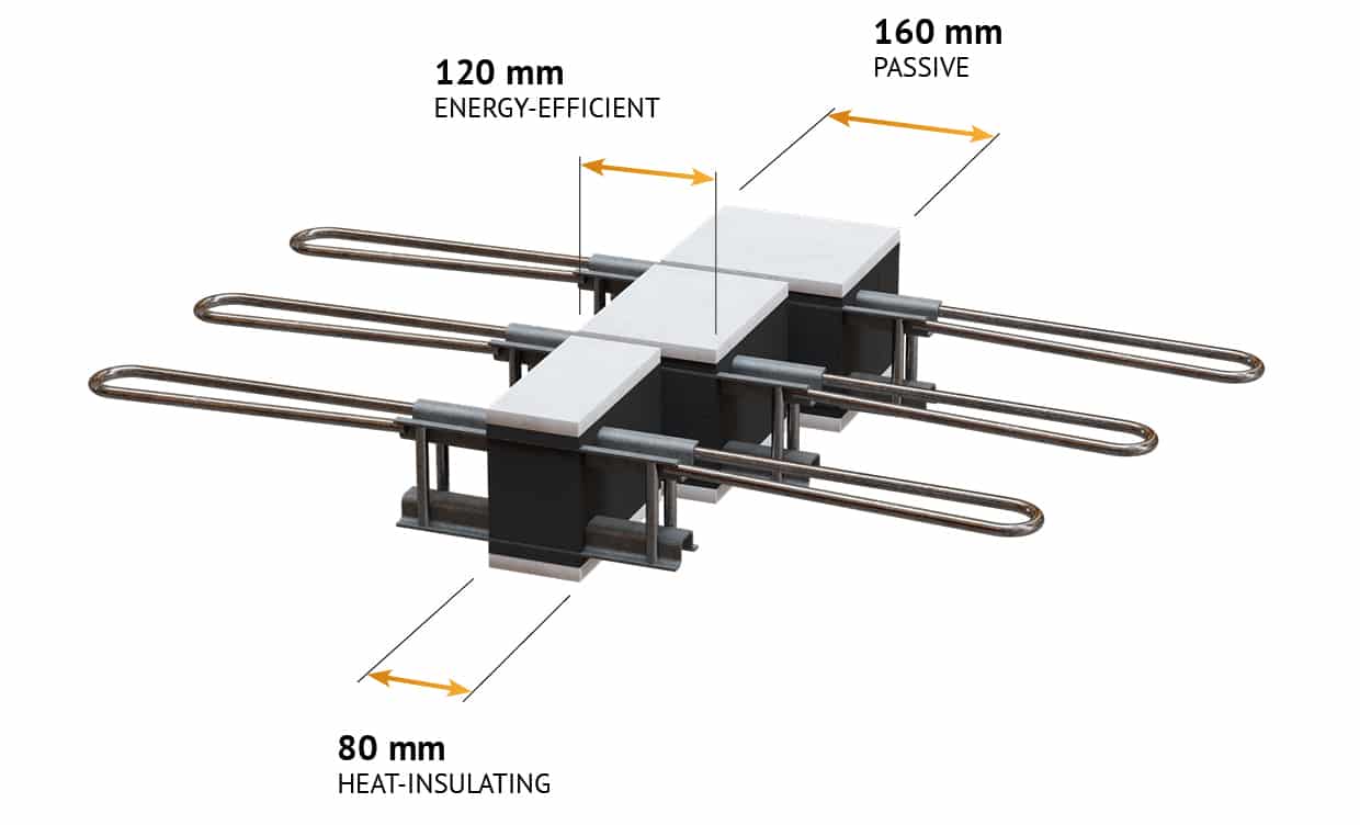
The patented design of the OMEGA load-bearing frames has allowed for an increase in the thickness of thermal insulation made from graphite-expanded polystyrene to up to 16 cm, while maintaining a fire resistance class of REI 120 for the connection.


None of the other known balcony connectors in the world can achieve the high thermal resistance and thermal conductivity values of the TIPOMEGA® system.
This high fire resistance is ensured by magnesium plates that are placed on all non-concrete surfaces of the linear joint, i.e. along the entire joint from the top and bottom of the connector, as well as on both lateral edges of the joint.

Magnesium plates are made from natural components: magnesium oxide, fiber cement, cellulose fibers, and expanded perlite. They are resistant to both frost and water, as well as to fungi, mold, and insects.

Ease of design, simplicity of assembly
The spacing of the OMEGA frames is selected so that their linear load-bearing capacity is no less than the calculated values of forces and moments in the connection, as determined through static and strength calculations.
About
At the same time, as the overhang decreases, the shear forces on the support generated by the balcony slab also decrease, thus requiring fewer frames.


If the anchor rods are also welded to the lower stainless steel profile, the OMEGA frame can transfer bending moments in both directions.

The innovative design of the OMEGA load-bearing frames enables their exceptionally wide application in balconies, canopies, cornices, beams, walls, columns, and other external structures.


In our design, we avoid the recently common practice on construction sites of using so-called inserts, bodies, or fillers between connectors. Continuous system insulation throughout the entire balcony-to-building connection is a hallmark of TIPOMEGA®.